 Bakvind
Installation guide
SIM7080G cellular modem
This guide is for people installing a cellular modem themselves. The modem lets a mobile node connect directly to Bakvind; a mobile gateway can also receive LoRa messages from several nodes.
← Back to Get startedChoose the right board
The modem board we recommend
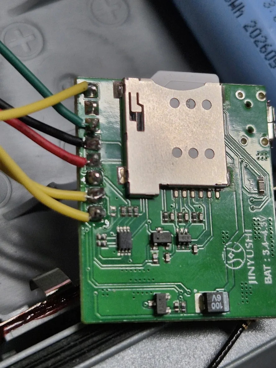
We recommend a board identical to the JINYUSHI SIM7080G board shown in the photos. Choose the version without GPS in the linked AliExpress listing. “SIM7080G” names the cellular chip itself; other carrier boards can have different power and control wiring. Compare the board, labels and pin order with the photos before connecting it.
See the modem on AliExpress (choose without GPS) ↗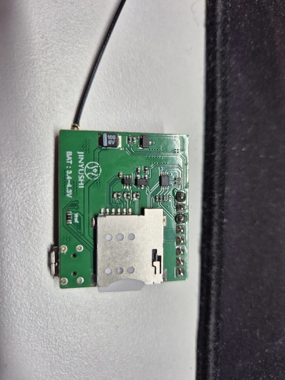
Power
BAT and 3.3 V depend on the modem board
On the pictured modem board, connect BAT to battery positive and GND to common ground. Leave the pin marked 3.3 V unconnected. This applies to the pictured board whether the host node is a Solar Node or a RAK. A different carrier board in the RAK lab setup did require 3.3 V for its logic. Follow the wiring verified for your exact modem variant.
Never connect modem BAT to a 3.3 V signal pin. Check polarity and battery voltage before inserting the SIM and starting the node.
SenseCAP Solar Node P1 / P1-Pro
Wiring for Solar Node
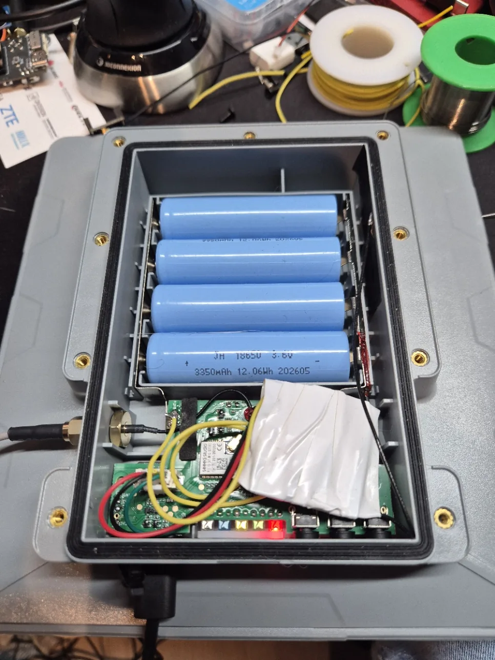
This wiring was tested on the modified Solar Node. The 4-pin Grove plug on the back uses only D0, D1 and GND. Leave 5 V unconnected: this modem board is not 5 V compatible. Remove the complete L76K GPS daughterboard to free the header pins.
| Solar Node | SIM7080G | Function |
|---|---|---|
| Grove pin 1 / D0 | TXD | Node receives from modem |
| Grove pin 2 / D1 | RXD | Node sends to modem |
| Grove pin 3 / 5 V | — | Not connected |
| Grove pin 4 / GND | GND | Common ground |
| GPS header D0/WUP | DTR | Controls modem wake/sleep |
| GPS header D6/RX | PWRKEY | Starts the modem |
| BAT+ on the Solar board | BAT | Direct battery supply |
| No connection | 3.3 V | Unconnected on the pictured board |

D0 and D1 are the data lines marked on the Solar Node board. Wire colours in the photos belong to one build and are not a standard.
The Solar Node connector follows the Grove standard: keyed HY2.0-4P with 2.0 mm pitch. Pins 1 and 2 are data, pin 3 is power and pin 4 is GND. The separately purchased plug must match this type; “4P” alone does not establish compatibility. Check the pin order before connecting the wires. Grove standard at Seeed Studio ↗ Plug used in this build (choose 4P) ↗
RAK4631 / RAK19003
Wiring for RAK WisBlock
Bakvind’s standard RAK setup uses a RAK4631 on a RAK19003 base board. The table shows the signals used by the firmware. These signals were tested with a different SIM7080G carrier board; the exact board in the photos has so far only been verified in the Solar Node.
| RAK19003 | SIM7080G | Function |
|---|---|---|
| RAK19003 UART RX0 / P0.20 | TXD | Node receives from modem |
| RAK19003 UART TX0 / P0.19 | RXD | Node sends to modem |
| SCL / P0.14 | DTR | Controls modem wake/sleep |
| SDA / P0.13 | PWRKEY | Starts the modem |
| RAK GND | GND | Common ground |
| Battery positive pad on the underside of RAK19003 | BAT | Direct battery supply |
On RAK19003, solder the BAT lead to the battery pad on the underside of the base board. The larger RAK19007 base board has a dedicated BAT pin, but its UART wiring may differ. Check the base-board revision before connecting it.